
1- Entity : Entity in database can be said like an object in object oriented program. Here we will take example of movie database . In E-R relationship diagrams they are represented by rectangles.
In the movie database the entities are : movie, stars and studios.
2 – Attributes : They are like properties of an entity . For example movie entity can have attributes like : Title, length. They are represented by ovals.
3- Relationships : The two entities movie and stars can have relationship or can have a connection with each other. The relationship between two entities can be represented by diamond.
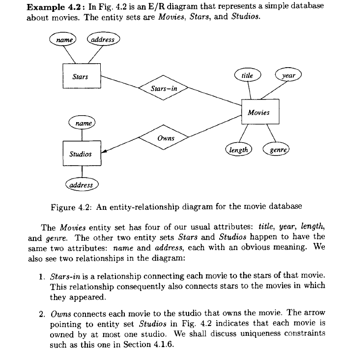
Note here , the arrow towards the studios represents that studio owns a movie .
1 – One to One Relationship : Remember that the arrow means “at most one” .
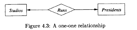
Here a president can run only one studio and a studio has only one president, so this relationship is one-one, as indicated by the two arrows, one entering each entity set.
2 – Many to one Relationships :

We have an arrow pointing to entity set Studios, indicating that for a particular star and movie, there is only one studio with which the star has contracted for that movie. However, there are no arrows pointing to entity sets Stars or Movies. A studio may contract with several stars for a movie, and a star may contract with one studio for more than one movie.
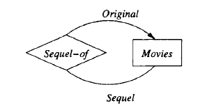
Another relationship can be is a relationship Sequel-of between the entity set Movies and itself. Each relationship is between two movies, one of which is the sequel of the other. To differentiate the two movies in a relationship, one line is labeled by the role Original and one by the role Sequel, indicating the original movie and its sequel, respectively. We assume that a movie may have many sequels, but for each sequel there is only one original movie.
Attributes on Relationships
Sometimes it is conwmient. or even essential, to associate attributes with a
relationship, rather than with any one of the entity sets that the relationship
connects. For example. consider the relationship of Fig. 4.4, which represents
contracts between a star and ~tudio for a rnovie. 1 We might wish to record the
salary associated with this contract. However, we cannot associate it with the
star; a star might get different salaries for different movies. Similarly, it does
not make sense to associate the salary with a studio (they may pay different
salaries to different stars) or with a movie (different stars in a movie may receive
different salaries).
However, we can associate a unique salary with the (star, movie, studio)
triple in the relationship set for the Contracts relationship .
Salaries becomes the fourth entity set of relationship Contracts. The whole diagram is shown in Fig.
Notice that there is an arrow into the Salaries entity set in Fig. 4.8. That
arrow is appropriate, since we know that the salary is determined by all the other
entity sets involved in the relationship. In general, when we do a conversion
from attributes on a relationship to an additional entity set, we place an arrow
into that entity set.

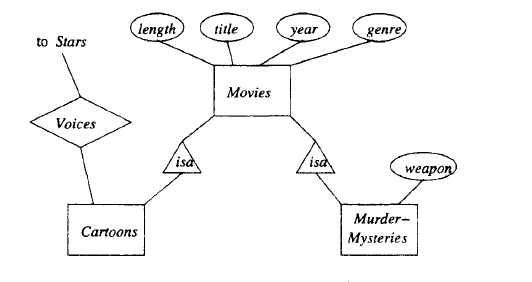
Subclasses in the E/R Model :
Often, an entity set contains certain entities that have special properties not associated with all members of the set. If so, we find it useful to define certain special-case entity sets, or subclasses, each with its own special attributes and/or relationships. We connect an entity set to its subclasses using a relationship called isa (i.e., “an A is a B” expresses an “isa” relationship from entity set A to entity set B).
An isa relationship is a special kind of relationship, and to emphasize that
it is unlike other relationships, we use a special notation: a triangle. One side
of the triangle is attached to the subclass, and the opposite point is connected
to the superclass. Every isa relationship is one-one, although we shall not draw
the two arrows that are associated with other one-one relationships.
Weak Entity Sets :
It is possible for an entity set’s key to be composed of attributes, some or all
of which belong to another entity set. Such an entity set is called a weak entity
set.
Causes of Weak Entity Sets : There are two principal reasons we need weak entity sets. First, sometimes entity sets fall into a hierarchy based on classifications unrelated to the “isa hierarchy” .
Exainple 4.20: A movie studio might have several film crews. The crews
might be designated by a given studio as crew 1, crew 2, and so on. However,
other studios might use the same designations for crews, so the attribute number
is not a key for crews. Rather, to name a crew uniquely, we need to give
both the name of the studio to which it belongs and the number of the crew.
The situation is suggested by Fig. 4.20. The double-rectangle indicates a weak
entity set, and the double-diamond indicates a many-one relationship that helps
provide the key for the weak entity set. The notation will be explained further
in Section 4.4.3. The key for weak entity set Crews is its own number attribute
and the name attribute of the unique studio to which the crew is related by the
many-one Unit-of relationship.

Two or more genera may have species with the same species name. Thus, to
designate a species uniquely we need both the species name and the name of the
genus to which the species is related by the Belongs-to relationship, as suggested
in Fig. 4.21. Species is a weak entity set whose key comes partially from its
genus.

Associations :
A binary relationship between classes is called an association. There is no analog of multiway relationships in UML. Rather, a multi way relationship has to be broken into binary relationships, which as we suggested in Section 4.1.10, can always be done. The interpretation of an association is exactly what we described for relationships in Section 4.1.5 on relationship sets. The association is a set of pairs of objects, one from each of the classes it connects.

Example 4.37: The UML diagram of Fig. 4.37 is intended to mirror the E/R diagram of Fig. 4.18. Here, we see assumptions somewhat different from those in Example 4.36, about the numbers of movies and studios that can be associated. The label 1..* at the Movies end of Owns says that each studio must own at least one movie (or else it isn’t really a studio). There is still no upper limit on how many movies a studio can own.
At the Studios end of Owns, we see the label 1..1. That label says that a movie must be owned by one studio and only one studio. It is not possible for a movie not to be owned by any studio, as was possible in Fig. 4.36. The label 1..1 says exactly what the rounded arrow in E/R diagrams says.
We also see the association Runs between studios and presidents. At the Studios end we see label 1..1. That is, a president must be the president of one and only one studio. That label reflects the same constraint as the rounded arrow from Presidents to Studios in Fig. 4.18. At the other end of association Runs is the label 0 .. 1. That label says that a studio can have at most one president, but it could not have a president at some time. This constraint is exactly the constraint of a pointed arrow.

Self-Associations:
An association can have both ends at the same class; such an association is
called a self-association .
Example 4.38: Figure 4.38 represents the relationship “sequel-of’ on movies. We see one association with each end at the class Movies. The end with role TheOriginal points to the original movie, and it has label 0 .. 1. That is, for a movie to be a sequel, there has to be exactly one movie that was the original. However, some movies are not sequels of any movie. The other role, TheSequel has label 0 .. *. The reasoning is that an original can have any number of sequels. Note we take the point of view that there is an original movie for any sequence of sequels, and a sequel is a sequel of the original, not of the previous movie in the sequence. For instance, Rocky II through Rocky V are sequels of Rocky. We do not assume Rocky IV is a sequel of Rocky III, and so on.

Aggregations and Compositions :
An aggregation is a line between two classes that ends in an open diamond at one end. The implication of the diamond is that the label at that end must be 0 .. 1, i.e., the aggregation is a many-one association from the class at the opposite end to the class at the diamond end. Although the aggregation is an association, we do not need to name it, since in practice that name will never be used in a relational implementation.
A composition is similar to an association, but the label at the diamond end must be 1..1. That is, every object at the opposite end from the diamond must be connected to exactly one object at the diamond end. Compositions are distinguished by making the diamond be solid black.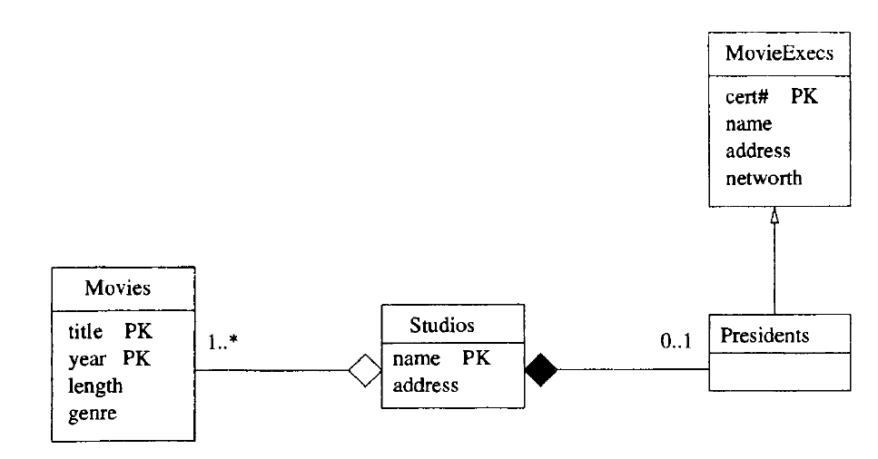
Link for more example on aggregation and composition.
https://www.visual-paradigm.com/guide/uml-unified-modeling-language/uml-aggregation-vs-composition/
Cardinality :
The cardinality of the relationship describes the number of tuples (rows) on each side of the relationship.
Either side of the relationship may be restricted to allow zero, one, or multiple tuples.
The type of key enforces the restriction of multiple tuples. Primary keys are by definition unique and enforce the single-tuple restriction, whereas foreign keys permit multiple tuples.

One-to-many pattern : By far the most common relationship is a one-to-many relationship; this is the classic parent-child relationship. Several tuples (rows) in the secondary entity relate to a single tuple in the primary entity. The relationship is between the primary entity’s primary key and the secondary entity’s foreign key .
For instance : each base camp may have several tours that originate from it. Each tour may originate from only one base camp, so the relationship is modeled as one base camp relating to multiple tours. The relationship is made between the BaseCamp’s primary key and the Tour entity’s BaseCampID foreign key, as diagrammed in Figure 3-5. Each Tour’s foreign key attribute contains a copy of its BaseCamp’s primary key.
The one-to-many relationship relates zero to many tuples (rows) in the secondary entity to a single tuple in the primary entity.

One-to-one pattern :
One-to-one relationships connect two entities with primary keys at both entities. Because a primary key must be unique, each side of the relationship is restricted to one tuple .
Many-to-many pattern :
In a many-to-many relationship, both sides may relate to multiple tuples (rows) on the other side of the relationship. The many-to-many relationship is common in reality, as shown in the following examples:
The many-to-many logical model shows multiple tuples on both ends of the relationship. Many-to-many relationships are nearly always optional. For example, the many customers-to-many events relationship is optional because the customer and the tour/event are each valid without the other .
To implement a many-to-many relationship in SQL DDL, a third table, called an associative table (sometimes called a junction table) is used, which artificially creates two one-to-many relationships between the two entities (see Figure 3-8).
Figure shows the associative entity with data to illustrate how it has a foreign key to each of the two many-to-many primary entities. This enables each primary entity to assume a one-to-many relationship with the other entity.
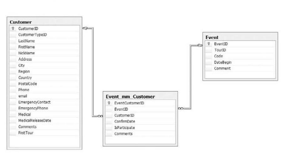
In the associative entity (Customer_mm_Event), each customer can be represented multiple times, which creates an artificial one-event-to-many-customers relationship. Likewise, each event can be listed multiple times in the associative entity, creating a one-customer-to-many-events relationship.

Supertype/subtype pattern
One of my favorite design patterns, that I don’t see used often enough, is the supertype/subtype pattern.
It supports generalization, and I use it extensively in my designs. The supertype/subtype pattern is also perfectly suited to modeling an object-oriented design in a relational database.
The supertype/subtype relationship leverages the one-to-one relationship to connect one supertype entity with one or more subtype entities. This extends the supertype entity with what appears to be flexible attributes.
The textbook example is a database that needs to store multiple types of contacts. All contacts have basic contact data such as name, location, phone number, and so on. Some contacts are customers with customer attributes (credit limits, loyalty programs, etc.). Some contacts are vendors with vendor-specific data.

Reference from First course in Database by J.D Ullman .
